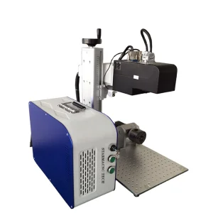
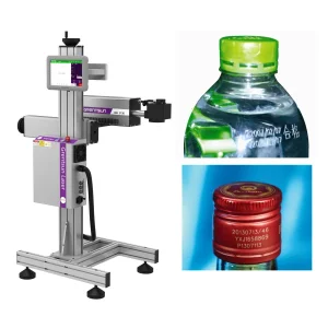
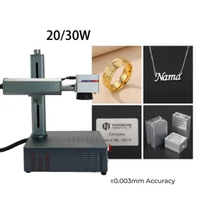
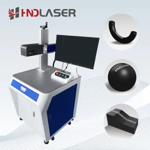
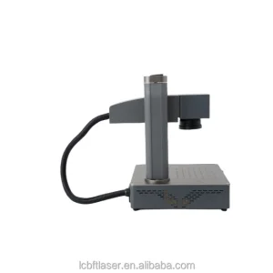
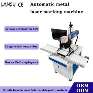
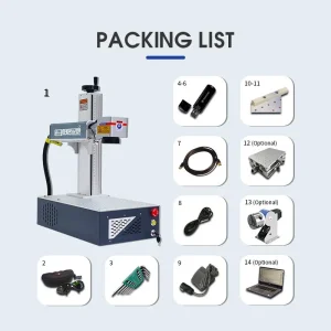
The industrial laser manufacturing paradigm has experienced a profound shift over the past decade. Historically, laser systems operated using basic analog control methodologies, where pulse generators acted independently from mechanical motion stages. Modern smart manufacturing, governed by the demands of Industry 4.0, requires high-efficiency control architectures where the Laser Control Unit (LCU) serves as the primary processing engine.
Today, global manufacturing demands high throughput combined with sub-micron spatial accuracy. A Laser Control Unit acts as the bridge connecting high-level CAD/CAM software to real-time hardware execution. By translating digital vectorized pathways into synchronized control protocols—such as the XY2-100 digital standard, SL2-100, and fiber bus topologies—modern controllers manipulate laser emission and scan-head mirror movements within microsecond frames.
Geographically, the expansion of high-speed manufacturing lines in East Asia, North America, and Europe has accelerated the consumption of smart laser systems. The shift from standard Q-switched fiber lasers to sophisticated MOPA (Master Oscillator Power Amplifier) setups requires advanced control units that can modulate pulse duration from 2ns to 500ns on the fly. This precision enables engineers to control thermal accumulation during cutting, drilling, and color marking of polymers, ceramics, and metallic alloys.
Industrial-grade Laser Control Units run on dual-processor architectures where a high-performance Digital Signal Processor (DSP) handles interface operations, data parsing, and user interactions, while a Field-Programmable Gate Array (FPGA) manages real-time hardware execution. This division of labor prevents operating system latency from interfering with the laser process, protecting sensitive hardware from tracking errors.
As a scan-head mirror accelerates and decelerates, physical inertia creates path errors at corners. Advanced control units use specialized math routines—including Laser Delay, Mark Delay, Poly Delay, and Jump Delay—to offset these dynamic lag states. This ensures that the laser triggers only when the galvo mirror is moving at the correct speed, preventing burn marks at corners.
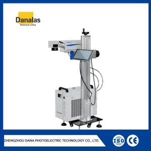
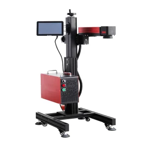
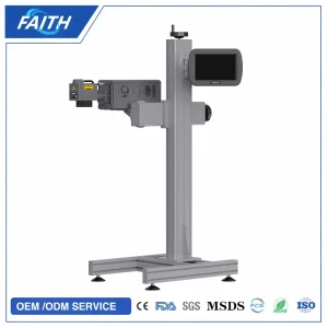
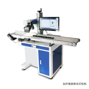
For processing parts on high-speed conveyor belts, the LCU reads raw input from rotary encoders and optical triggers. The card processes encoder pulses directly on the hardware chip to track movement along the X or Y axis in real time. It shifts the laser command coordinates to match the conveyor's speed, maintaining layout alignment at feed rates up to 60 meters per minute.
As the industrial sector moves toward fully automated smart factories, laser control boards must integrate with wider factory networks. Traditional USB boards are being replaced by Ethernet-based controllers and EtherCAT bus configurations. This allows developers to link multiple control cards to a central workstation or PLC, reducing electrical interference and simplifying wiring.
Integrating vision-guided systems with laser controllers has also become standard practice. Modern control cards support direct input from CCD camera sensors. This enables automatic shape detection, orientation tracking, and real-time correction. It eliminates the need for precision alignment jigs, as the laser adjust its path automatically based on the workpiece's actual position.
Hangzhou Kinray Laser Co., Ltd. is a leading China industrial laser marking machine manufacturer specializing in advanced fiber and UV laser solutions for global manufacturing industries. With a strong focus on innovation, precision, and intelligent manufacturing, Kinray Laser is committed to delivering high-performance laser equipment that improves production efficiency, product traceability, and marking quality.
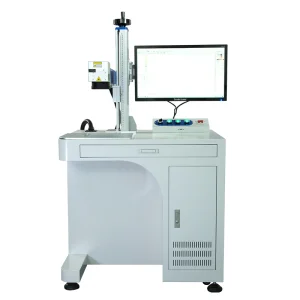
Located in Hangzhou, China, the company integrates research and development, manufacturing, sales, and technical support to provide comprehensive laser processing solutions for customers worldwide. Our extensive product portfolio includes fiber laser marking machines, UV laser marking machines, CO2 laser marking systems, MOPA laser markers, flying laser marking machines, 3D laser marking equipment, and customized automated laser solutions.
Kinray Laser products are widely used in electronics, automotive, medical devices, precision hardware, jewelry, packaging, aerospace, consumer goods, and industrial manufacturing industries. Designed for high-speed, high-precision, and permanent marking applications, our systems are capable of processing a wide range of materials, including metals, plastics, ceramics, glass, and composite materials.
Equipped with advanced production facilities and rigorous quality management systems, Kinray Laser maintains strict quality control throughout every stage of manufacturing. Each machine undergoes comprehensive testing to ensure stable performance, reliability, and compliance with international standards.
To support global customers, we offer flexible OEM and ODM services for distributors, system integrators, equipment brands, and industrial manufacturers. Our experienced engineering team works closely with customers to develop customized laser solutions tailored to specific production requirements, automation needs, and industry applications.
Driven by technological innovation and customer satisfaction, Hangzhou Kinray Laser Co., Ltd. continues to expand its global presence and strives to become a trusted partner for intelligent laser processing solutions, helping manufacturers achieve smarter, more efficient, and sustainable production.
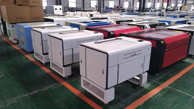
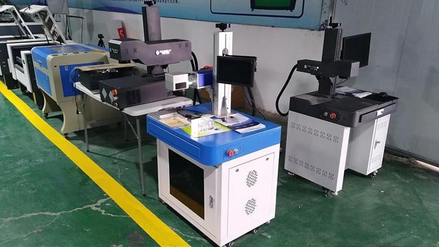
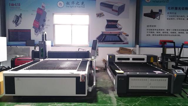
PC-based LCUs rely on a host computer to process software commands, sending raw coordinate lists to the control board via USB or Ethernet. Stand-alone (embedded) control units store files and process job tasks directly on their integrated processors. Embedded systems offer greater stability in heavy industrial environments by removing the risk of computer operating system crashes, while PC-based systems offer more interface customization options.
XY2-100 is an industry-standard serial digital protocol that transmits 16-bit scan-head coordinate data over differential channels. Digital signals reduce noise susceptibility over long wire runs, prevent position drift, and eliminate the grounding loops common to analog control boards. This ensures stable, high-speed beam positioning.
Yes. Our advanced control boards interface directly with machine vision cameras via high-speed communication ports. The system captures image data, adjusts for target rotation and shift, and updates the marking coordinates in real time. This enables automated, high-precision alignment on moving conveyor belts or randomly positioned workpieces.
MOTF allows the laser to mark items moving on a conveyor belt. The control unit requires direct hardware connections for a rotary encoder (to track belt speed) and an optical photo-sensor (to detect the arriving part). The board's internal FPGA calculates target displacement in real time to prevent layout distortion during marking.
Because scan-head mirrors have physical inertia, their movement lags behind electrical commands. Adjusting Jump and Poly delays ensures the galvo mirror is positioned correctly before the laser fires. This prevents "burn tails" at the start of vectors and "rounded corners" on geometric shapes.
Yes. Our control cards feature dedicated digital control ports that communicate with MOPA laser engines. They allow independent software control over both pulse frequency and pulse width (ranging from 2ns to 500ns). This flexibility enables precise heat management when marking delicate plastics or engraving colors on stainless steel.
We support various industrial communication options, including standard DB25 interfaces, RS232, TCP/IP Ethernet, and custom digital I/O lines. For complex automated environments, our boards integrate with Modbus and EtherCAT protocols to simplify communication with PLCs and master controllers.
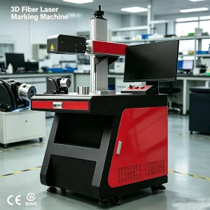
Our 3D-capable control boards drive a third dynamic axis (Z-axis linear actuator) alongside the traditional X and Y galvos. The card calculates focal shifts in real time to match the curvature of 3D parts. This maintains a consistent spot size across curved, sloped, or multi-level surfaces.
 Kinray Laser